


The SHIP setup

SHIP 3D navigation! (2.2MB)
Adobe Reader or higher as well as Microsoft DirectX (Windows) or OpenGL (Mac) ist needed!
For navigation info click on "Info" button in PDF!
Technical information about the Velocity Filter (SHIP)
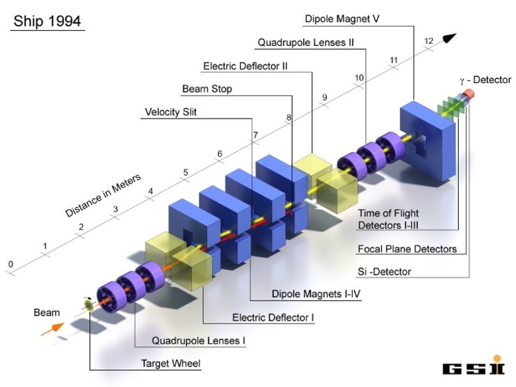
This is the SHIP setup in it's 1994 modified version:
The target wheel

For the production of super heavy elements via the "cold fusion process" at SHIP Pb and Bi targets are employed. Their low melting points are one of the major bottlenecks of the production of SHE limiting the maximum beam current (presently ~ 0.3 particle mA = 2.1012 particles/s). To increase the interaction surface of the beam on target the 8 foils (~ (20 . 120) mm) are mounted on a wheel (31cm in diameter) rotating through the beam in order to distribute the beam power onto a large area. In addition a passive cooling in terms of two cooled metal sheets in front of and behind the target is installed carrying away the heat radiation from the targets. The low cross section regime (<1pb = 1 SHE event/10days) for the synthesis of SHE requires even higher beam intensities than the ones accepted right now by the SHIP target wheels. Therefore, an intensive development program is underway to test and develop an active target cooling via a gas jet. Chemical Pb and Bi compounds providing higher melting points are also under investigation. Some of the projectiles (1 pb : 1 fusion per ~ 3. 1018 particles) coming from the UNILAC fuse with a target particle and build an excited compound nucleus (CN). The CN is cooled by particle evaporation (for SHE typically 1 neutron) and γ ray emission and leaves the target foil in beam direction.

Target wheel SHIP
(click to enlarge)
The quadropole lenses


The evaporation residues leave the target foils with an angular divergence, due to scattering in the target material and due to the evaporation of particles. To focus the beam and collect particles from a solid angle as big as possible, two electro-magnetic lenses realised as quadrupole triplets are used at the beginning and towards the end of the ion-optical setup.
| Specifications: | |
| aperture radius: | 7.5 cm |
| pole length: | 25 cm |
| maximum gradient: | 9.5 T/m |
The velocity filter

The reaction products leave the target with velocities which are smaller than the velocity of the projectiles passing the target without interaction. This is due to the conservation of momentum: The heavy evaporation residues have the same momentum as the light projectiles and therefore less velocity. If mp and mt are the masses of projectile and target nucleus and vp is the velocity of the incoming projectile one gets vCN = [mp/(mp+mt)].v p for the velocity of the compound nucleus. A velocity filter exploits this fact to separate the reaction products from elastically scattered beam particles and other reaction products from inelastic and deep inelastic processes like nucleon transfer, multinucleon transfer and incomplete fusion. The remaining background of these species can be further suppressed by the tof-energy technique using the transmission detectors and the stop arry.
The main part of the velocity filter consists of electric deflectors and dipole magnets. The comparison of the (magnetic) Lorentzian force and the electric force of perpendicular magnetic and electric fields (crossed fields) yields a velocity dependence in the sense that for each velocity vi a combination of forces can be found with a resulting force 0:
- Fmag = q.v.B
- Fel = q.E
- Fmag = Fel → Ftot = 0 ; ∀ vi
i.e. a special choice of the ratio E/B selects one single velocity which allows particles to pass the filter - independent of their charge. In contrast to a classical Wien (velocity) filter with superimposed crossed fields SHIP is for efficiency reasons built as a velocity filter with separated fields (2 electrostatic fields E1 and E2 and 4 dipole magnets M1-M4) in a mirrorsymmetric arrangement with respect to central separation plane - the velocity dispersion plane. In this place a pair of slits is mounted which provides the possibility to further spatially restrict the transmitted particles while the beam is deflected onto a cooled copper plate as beam stop. Here the charge of the stopped particles is collected for normalization purposes.
| Specifications (E-fields): | |
| gap: | 15 cm |
| plate dimensions: | (50.50) cm² |
| maximum voltage: | ± 330 kV |
| Specifications (B-fields): | |
| pole dimensions: | (40.50)cm² (3 magnets) (40.65) cm² (1 magnet) |
| gap: | 15 cm |
| maximum field: | 0.7 T |
| magnetic rigidity: | 1.2 Tm |
The bending magnet M5

The fifth dipole magnet M5 deflects the beam 7.5°. This helps to further reduce the background: Low charge and high velocity may cause some of the projectiles to pass the velocity filter. These particles have a higher magnetic rigidity and they are deflected less than the reaction products by the dipole magnet. They are implanted mainly on the right hand side of the stop detector. On the other hand low-energetic projectiles, which passed through the filter because of their velocity being similar to that of the reaction products, are deflected to the left hand side.
The SHIP detectors

The time of flight detector
The time of flight (tof) detector array consists of two or three (dependent on the energy of the evaporation residues) units. A pair of thin carbon foils (thickness ~0.03 μg/cm²) is combined with a pair micro channel plates (MCP).
A charged particle creates secondary electrons while passing through the first C-foil. The e- are accelerated by an electrostatic field in beam direction and deflected 180° onto the microchannel plates by a perpendicular magnetic field. The charge of electrons multiplied in the MCP is then collected on a final anode.
The transmission detector provides the START signal for a time-of-flight (tof) measurement with the STOP signal coming from the stop array in order to distinguish decays occurring inside it like α decays or fission of the implanted reaction products and/or their daughter nuclei from background events like scattered beam particles and others coming from upstream. The efficiency of the tof detector array is 99.8% and it has typical timing resolution of 700 ps.

The time of flight (tof) detector at SHIP
(click to enlarge)
For further details see:
Large size foil-microchannel plate timing detectors
S.Saro, R.Janik, S.Hofmann, H.Folger, F.P.Heßberger, V.Ninov, H.J.Schött, A.P.Kabachenko, A.G.Popeko, A.V.Yeremin
Nucl. Instr. Methods in Phys. Research A 381 (1996) 520
The Stop-detector
The stop detector array consists of seven identical 16-strip silicon detectors and three germanium detectors. The active area of each silicon wafer is (35.80) mm². Each strip is 5 mm wide and position sensitive in the vertical direction with a relative resolution of 150 μm full width at half maximum for the α decays of a decay chain. For that reason, the stop detector is equivalent to 3700 single detectors, each with a 100% active area of (0.15.5) mm². The energy resolution is 14 keV for α particles from a 241Am source or α decays of implanted nuclei. Six wafers are mounted in the back hemisphere facing the stop detector. They measure escaping α particles or fission fragments with a solid angle of 80% of 2π. In the case of the back detectors, neighboring strips are connected galvanically, forming 28 energy-sensitive segments. The direction of the escaping α particle or fission fragment can be roughly retraced. The energy resolution obtained by summing the energy-loss signal from the stop detector and the residual energy from the back detector is 40 keV for α particles. All silicon detectors are cooled to 263 K.
The germanium detectors measure x rays or γ rays that are coincident within a time window of 4 μs with signals from the silicon detectors. This allows for the detection of α transitions to excited levels in the daughter nucleus, which decay by gamma emission. In the case of an electron conversion process, characteristic x rays may be emitted, which would allow for a clear element identification. Although the probability for detecting coincident events is small, the germanium detectors provide useful spectroscopic information if the cross sections are of the order of nanobarns or higher.

The stop detector at SHIP.
(click to enlarge)
For further details see:
The discovery of the heaviest elements
Hofmann, S. and Münzenberg, G.
Rev. Mod. Phys., 72, 733-767 2000