


Machine Control Group
Ring accelerators consist of a large number of individual devices. The overall functionality of the accelerator depends on the precise coordination of these components. This requires software that calculates time-dependent set values for all devices, taking into account the theoretical principles of accelerator physics, the real properties of the ion beam that occur during operation, and the technical characteristics of the devices. Additionally, the control system must provide suitable user interfaces, enabling operators to modify accelerator parameters to optimize beam performance.
The Machine Control Group within the department System Design SIS100/SIS18 is responsible for developing software systems to control the accelerators at the international accelerator facility FAIR.
Its members, who consist of physicists and two engineers, have a profound understanding of accelerator physics, extensive experience in operating accelerators, and many years of experience in developing machine control software.
They are also familiar with the functionality and interfaces of both the technical equipment and the control system. They maintain continuous cooperation with the technical specialist teams responsible for the equipment and control systems, as well as with operational staff.
The close cooperation between the Machine Control Group and the System Planning Group has proven to be highly effective for the control of ring accelerators. To develop control concepts for the accelerators, beam dynamics simulations are often necessary.
The employees of the System Planning Group make a significant contribution to this with their technical expertise in this field. On the other hand, the Machine Steering Group also supports the System Planning Group, for example in preparation and implementation of machine experiments for further development of accelerators.
~~~~~~~~~~~~~~~~~~~~~~~~~~~~~~~~~~~~~~~~~~~~~~~~~~~~~~~~~~~~~~~~~~~~~~~~~~~~~~~~~~~~~~~~~~~~~~~~~~~~~~~~~~~~~~~~~~~~~~~~~~~~~~~~~~~~~~~~~
What is meant by Machine Control?
The function of a ring accelerator can be described by various physical parameters. These include fundamental beam characteristics- such as ion type, energy, intensity, and emittances- as well as accelerator settings like the working point, ion-optical parameters, and the speed of the acceleration ramp. Additionally, details related to beam injection and extraction are crucial. Conversely, devices designed to influence the beam in specific ways are governed by technical parameters. For example, accelerator magnets are controlled via power supplies, with their operation determined by the time-dependent variation of current. Similarly, RF cavities require the gap voltage and frequency to be specified over time to ensure correct functionality.
One of the two central tasks of machine control is to translate the values for the physical parameters of the machine into consistent specifications for the temporal progression of the technical parameters of all devices, known as set values, so that the devices interact synchronously with the beam in the desired manner. This translation requires a machine model whose input parameters are the physical parameters of the accelerator and whose output parameters are the set values of all devices. To calculate the device set values from the physical parameters, accelerator physics relationships are used, taking into account the specific ion-optical properties of the accelerator, as well as device-specific data, such as the excitation curves of the magnets.
Since the devices of the accelerator always show unavoidable deviations from their idealized behavior in the theoretical models, each accelerator contains correction elements that are used to reduce the deviations from the ideal behavior. In addition to the physical parameters that describe the function of the accelerator, the machine model also provides physical parameters for the use of correction elements to correct expected deviations.
Indeed, deviations in the actual machine performance can only be predicted to a limited degree. While operational experience with accelerators is incorporated into the development of the machine model, in practical operation variations often occur that cannot be fully corrected using the model parameters alone. The beam's properties are verified at the accelerators through beam instrumentation devices. If measurements reveal discrepancies from the desired performance, correction values for suitable actuators can be calculated using accelerator physics principles to minimize these deviations. This secondary central task of machine control is executed by beam-based measurement and control systems.
Machine Modeling
The machine models for the international accelerator facility FAIR are implemented using the LSA framework (LHC Software Architecture). This framework was initially developed at CERN for the control of the LHC. It primarily consists of a database, a service program known as the LSA server, and a suite of applications. The database stores all necessary information for calculating set values, including device properties and ion optical data, as well as structures for modeling the accelerators. Additionally, it archives all calculated data. The LSA server handles computations that derive both intermediate values and device set values based on input parameters. The associated applications facilitate access to data within the LSA database and allow modifications to input values.
Parameters and Hierarchies
A key aspect of modeling with LSA involves the hierarchy of parameters, which explicitly represents the dependencies among various physical and technical variables. At the highest level of this hierarchy are the physical input parameters used to operate the machine. Conversely, at the base level are the set values of individual devices. Intermediate levels may include parameters that provide values of physical intermediate variables necessary for measurement evaluation or that facilitate the calculation of downstream parameters. The upward connections of a parameter indicate the parent parameters required for its calculation.
This hierarchical structure offers a clear visualization of how changes in one parameter can influence others, highlighting which parameters are affected by specific changes and which can induce changes within the system. While the device-related technical parameters, such as set values, are determined by the accelerator's design, all other parameters- including the physical input parameters- are defined freely by the modelers.
 into current and voltage profiles for the quadrupole power supplies")
Rules
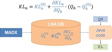
To derive parameter values from their parent parameters, rule sets are stored within the LSA framework. These rules encode the algorithms for calculating dependent parameters as Java code. At this stage, the underlying accelerator physics theory is formalized into explicit computational rules. Implementing these rules constitutes a critical responsibility for the model developers.


Data pertaining to optics, device specifications, and related information
Hierarchy and operational rules for ring accelerators can be designed in a largely standardized manner due to the fundamental similarities in their mode of operation. This allows for the use of a common code base for calculations across all ring accelerators. Such an approach greatly simplifies both implementation and maintenance efforts and is therefore employed wherever feasible in the modeling of accelerators at GSI and FAIR. However, individual accelerators naturally exhibit differences in various aspects, such as the specific properties of functionally comparable components- for example, the number and excitation curves of quadrupoles- as well as the limits of their associated power supplies. Additionally, differences arise in ion-optical design and initial input parameters. To address these variations, the LSA database includes detailed data for all devices and machine-specific information on ion optics and starting conditions. This machine-specific data is supplied by domain experts associated with each accelerator; for SIS18 and SIS100, these data collection and validation tasks are performed by members of the System Planning Group.
To determine the modification in quadrupole power supply set values resulting from adjustments to the input tune parameters, linear interpolation coefficients must be derived through ion-optical simulations and subsequently imported into the LSA database.
Depiction of Cycles (Contexts)
LSA introduces the concept of beam processes to describe the cycles within ring accelerators. A beam process corresponds to a specific segment of the cycle, characterized by an independent function such as injection, acceleration ramp, or extraction. A complete cycle is composed of a series of these beam processes, collectively referred to in LSA as a chain.

Settings
Parameters, hierarchy, and rules, along with data stored in the LSA database, form the foundation for calculating values of parameters. These values are represented in LSA as settings, which associate a specific value with a parameter and a beam process. Consequently, parameter values are segmented according to the beam process within LSA. The device settings, corresponding to set values, automatically transmitted to the devices during cycle setup and whenever modifications are made, are similarly divided into the respective beam processes. The timing system is responsible for initiating the execution of data in the correct temporal sequence by distributing events throughout the entire accelerator facility. To facilitate this, the model includes relevant rules and parameters to compute set values for the timing system.

User Interface
Calculations of the set values using the aforementioned structures are performed on the LSA server. As a service program, this setup does not provide direct user access. Therefore, user interfaces must be developed to enable users to display and modify model parameters. One of the primary user interfaces is the ParamModi application, which facilitates efficient access to all model input parameters and allows visualization of device set values, such as the time-dependent current values of a power supply. The selection and layout of input parameters within the interface are determined collaboratively by the modelers, machine experts, and operators.
The LSA architecture also supports the development of additional operational programs for specialized adjustment and optimization tasks. These programs utilize the same interface to the LSA server as ParamModi to modify model values and can incorporate measurement data, such as beam properties, to compute optimized parameter values. Such beam-based applications are actively being developed within the Machine Control Group.
