Power Converters
The Power Converter work package concerns the design, procurement, and testing of the power converters of all Super-FRS magnets.
Why Power Converters
The magnets in particle accelerators drive the beam and they need to be powered by a very stable current with a defined form and frequency. Therefore, high accuracy power converters are required to power the magnets. The input of the power converter is usually AC (from power grid) and the output is a DC voltage of required frequency and form to be applied to the magnet. As, in most of the cases, the magnetic field of the magnet is hard to be measured in real-time. Therefore, the beam is controlled by controlling the output current of the power converter. The current is measured with a highly accurate current transducer. This transducer employs zero-flux compensation techniques and is called DCCT (Direct-Current Current transformer).
See also:
Power Converter Set-up
Rather than a simple power supply, the power converter device must supply current and voltage to the magnet in a controlled way.
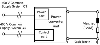
For this reason, it consists of a power part and a control part (Figure 1):
- Power part: It is supplied by a 400V AC, 3-phase Common supply system C3
- Control part: It is supplied by a 400V AC, 3-phase Common supply system C3
Power converters supply the loads (e.g. NC dipole magnet) through coaxial cables [1].
At the Super-FRS, power converters supply two different types of magnets as load:
- Normal conducting magnets (NC): electrically, an ohmic resistance R in series with an inductance L.
- Super conducting magnets (SC): electrically, an ohmic resistance R = 0 Ohm (in super conducting mode) in series with an inductance L.
Dipole, quadrupole and multipole magnets can be NC and SC. Steering magnets are all superconducting. In superconducting magnets a sudden loss of superconductivity can occur. This problem is called quench. For this, Quench Protection System (QPS) is foreseen in Super-FRS.
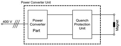
This system is responsible, in case of quench, to send the triggering signal to the PC in order to interrupt the supply of the magnet(s). Therefore, each power converter (Figure 1) which supplies to the superconducting magnets must be equipped with a Quench Protection Unit (see Figure 2).
The protection scheme is optimized to extract the magnet energy as fast as possible to protect the magnets and the current leads (used for superconducting connection of the magnets). For a more detailed description of the quench and QPUs of different power converter types please see here.
[1] In this context “Coaxial cable” implies to coaxial power cable.
Facts and numbers
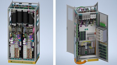
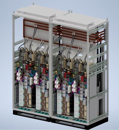
- Three cabinet types for all SC- and NC- power converters (PCs) (see figure 3 and figure 4):
- Type 1: two independent channels (50 kVA each) per cabinet;
- Type 2: three independent channels (10 kVA each) per cabinet;
- Type 3: up to three Type 1 cabinets internally connected in parallel.
- PCs for SC- magnets:
- 27 x FR.D2 Type 1 265A 14 cabinets [DCCT 10 ppm]
- 85 x FR.Q4 Type 1 315A 44 cabinets [DCCT 50 ppm]
- 106 x FR.C3 Type 2 300A 38 cabinets [DCCT 100 ppm]
- PCs for NC- magnets:
- 3 x FR.D1 Type 3 (2 x Type 1) 640A 6 cabinets [DCCT 10 ppm]
- 2 x FR.QoC1 Type 3 (2 x Type 1) 1000A 4 cabinets [DCCT 50 ppm]
- 2 x FR.QoC2 Type 3 (3 x Type 1) 1800A 6 cabinets [DCCT 50 ppm]
- 1 x FR.Q3 Type 3 (3 x Type 1) 1500A 3 cabinets [DCCT 50 ppm]
- Specially developed in GSI for the supply of sc- and nc- magnets
- Integrated quench detection and protection
- Modular design – compact and extendable for higher current
- Power factor correction (PFC) - sinusoidal mains currents, no reactive power, independent of mains voltage fluctuations
- Active front-end – energy feedback
- Two separate temperature chambers for the power unit and control unit with DCCT
- Local UPS
- Ventilation management with a heat exchanger
Location
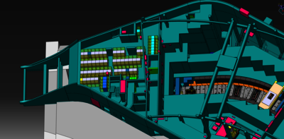
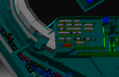
Super-FRS power converters will be located in building G018, at the fourth floor (E40) (Figure 5) and in building G006A, third floor (E30) (Figure 6).


