The department Ring HV is responsible for the procurement and subsequent operation of two new kicker systems for the future ring accelerator SIS100 of FAIR.
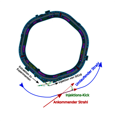
The SIS100 injection kicker directs the particles from the accelerator SIS18 onto the orbit of the SIS100 ring accelerator. The magnetic field of the injection-kicker has a vertical orientation, through which the particles obtain a horizontal kick. Figure 1 shows this process schematically as a top view of the SIS100.
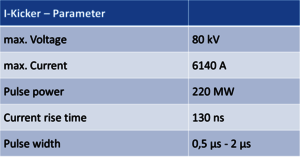
The basic circuit configuration is identical to the SIS18 kicker. The electrical parameters of the I-kicker can be found in Table 1
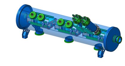
The injection kicker consists of six single magnets, which are located in a common vacuum chamber, which is shown in Figure 2.
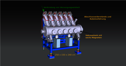
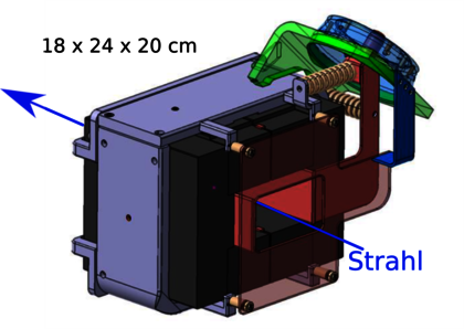
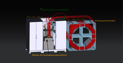
A magnet is shown in Figure 3. The copper coil with one winding as well as the magnet yoke made of ferrite material can be seen. Each of the six magnets has its own power supply unit (Figure 4) consisting essentially of a high-voltage power supply, high-voltage switches, control electronics and the pulse-forming energy storage. In case of the I-Kicker, the energy storage device is a coaxial cable with a length of approx. 200 m.
The Extraction- and Emergency-kicker is a bipolar kicker, which gives a vertical kick up or down. The kick upwards is for normal operation, during which the beam is deflected in the direction of the experimental sites and storage rings. The downwards-kick is only used in cases where the beam has to be stopped unexpectedly in order to avoid damage to the system.
These emergencies can occur for example due to the failure of individual accelerator components. To be able to implement two kicking directions with one magnet system, the circuit of the kicker already introduced must be modified.
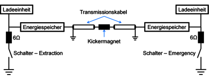
Figure 5 shows the circuit of the EE-kicker.
The main difference is, that two energy storages are used between which the kicker magnet is located. Depending on which switch is actuated, the direction of the current flow and thus, the magnetic field direction and kick direction can be influenced.
The electrical data are identical to the injection-kicker with a current of 6140 A and a voltage of 80. The current rise time is 900 ns and the maximum pulse length is 7 μs. Due to the longer pulse length, cables would occupy too much space as energy storage. Instead of a cable, a pulse-forming network with capacitances and inductances is used, which allows a higher energy density.
The EE-kicker consists of eight magnets, which are distributed in three vacuum tanks. In two vacuum tanks there is a triple group and a third tank contains two magnets.
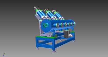
Figure 6 and Figure 7 show conceptual models of the EE-kicker. It can be seen that, in contrast to the injection-kicker, a magnet requires two cable feeds due to the circuit topology.
